Sculptform Facade Blades
FACADE BLADES
FACADE BLADES
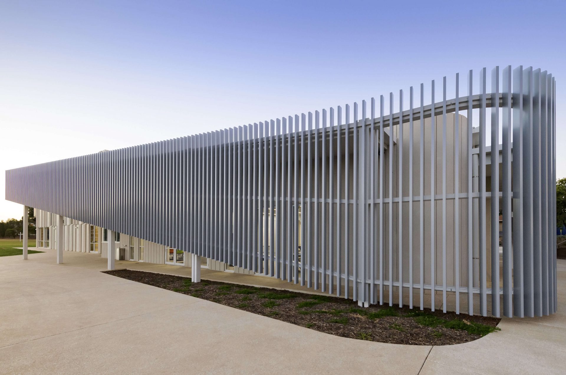
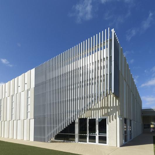
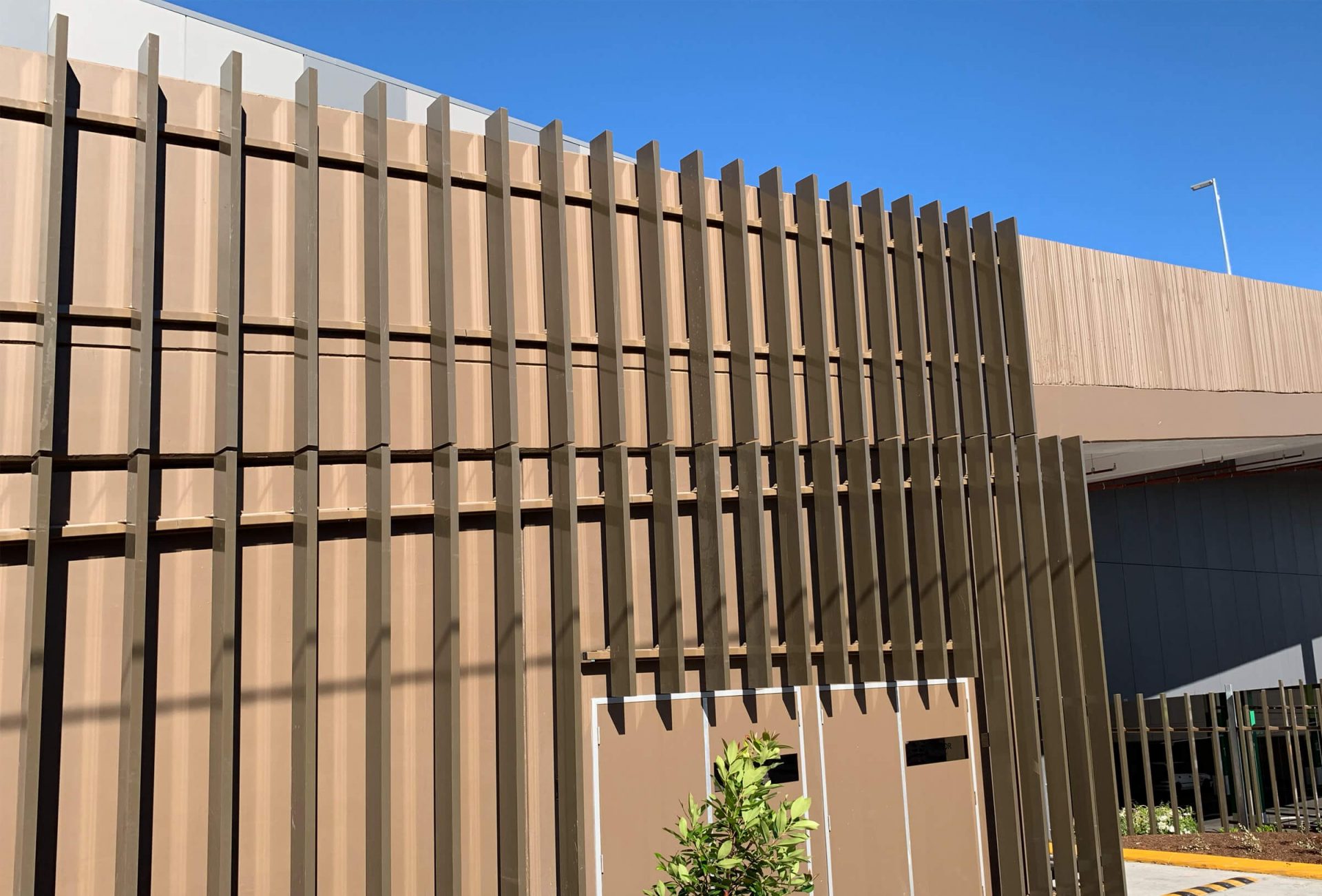
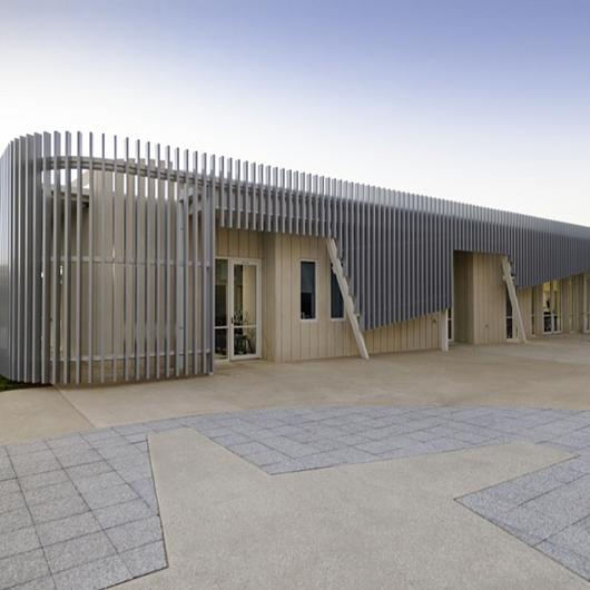
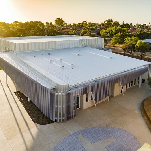
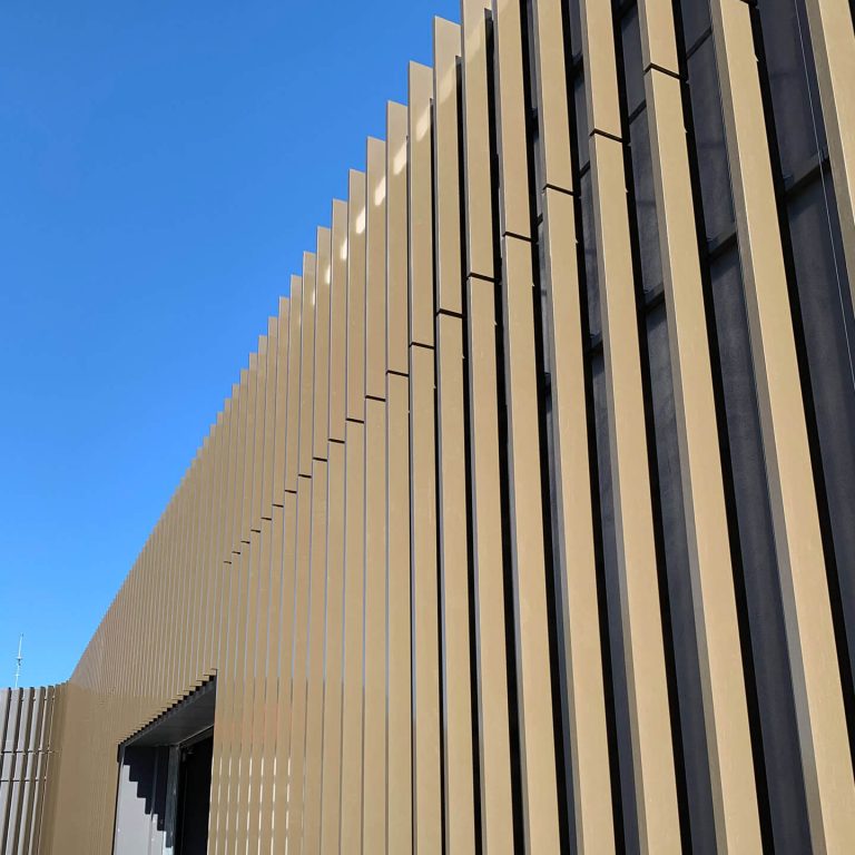
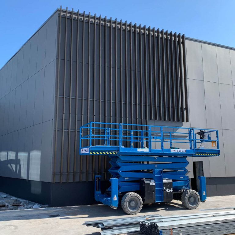
A facade blade system specifically designed and engineered for large scale external facades. Allowing large spans between fixings, the system is robust enough to accommodate a range of applications.
“The Facade Blade system really changes the appearance of the structure, by adding depth and contrast. It’s a very clean install with little or no fixings visible, with great performance.”
INFORMATION
MAXIMUM RAIL CURVE
3 metre radius
ALLOY/TEMPER
6060 - T6
FINISHES AVAILABLE
- Anodised
- Powder coated
WALL THICKNESS
- 2.2mm, ±0.25mm
- 2.2mm, ±0.25mm
- 2.5mm, ±0.25mm
- 2.0mm, ±0.25mm
SIZES
- 50x150mm
- 50x200mm
- 50x300mm
- 100x150mm
BRAND
Sculptform
MATERIAL
Extruded Australian Aluminium
ALUMINIUM MOUNTING RAIL
- 50x50mm (direct fix), 50x90mm (rail spanning)
- Diecast Aluminium (ADC12)
- Can be powder coated to suit required colour for project.
APPROX. WEIGHT
- 3.756kg p/lm
- 4.35kg p/lm
- 6.023kg p/lm
- 4.609kg p/lm
MAINTENANCE AND CLEANING
-Aluminium is a relatively low maintenance solution for any facade application. Maintenance largely depends on the degree of exposure, location of the project, and the coating used on the blades. Generally, no cleaning is required; however a typical schedule could include a visual inspection every 12 months to ensure there are no adverse environmental effects. -Surface dirt/dust, spider webs, bird droppings, rain spots and other debris, while not harmful can be unattractive and reduce the visual impact of a facade. A soft bristle broom or brush can be used to wipe the facade. Water can be used to aid the process but do not use harsh chemical cleaners as in some cases, coated layers can be removed. -Industrial and coastal environments will require a more frequent maintenance schedule to inspect for salt, visual deposits etc.
HOW IT WORKS
INSTALLATION
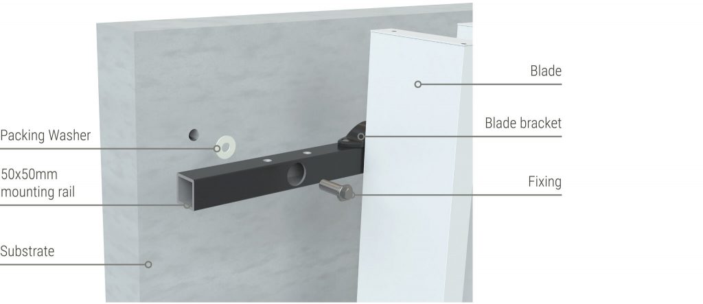
-The key to the system is the mounting rail, which is fixed to the structure at the required spacing and has preset locations for the blade sequence. -Prefinished blades are then easily connected to the mounting rail. The system has been designed to maximise design flexibility while maintaining ease of installation.
PRE-ENGINEERED CONNECTIONS
Working with leaders in the facade industry, we have created a world-class, pre-engineered system. For designers, this means large spans which allow uninterrupted linear looks.
THE SYSTEM
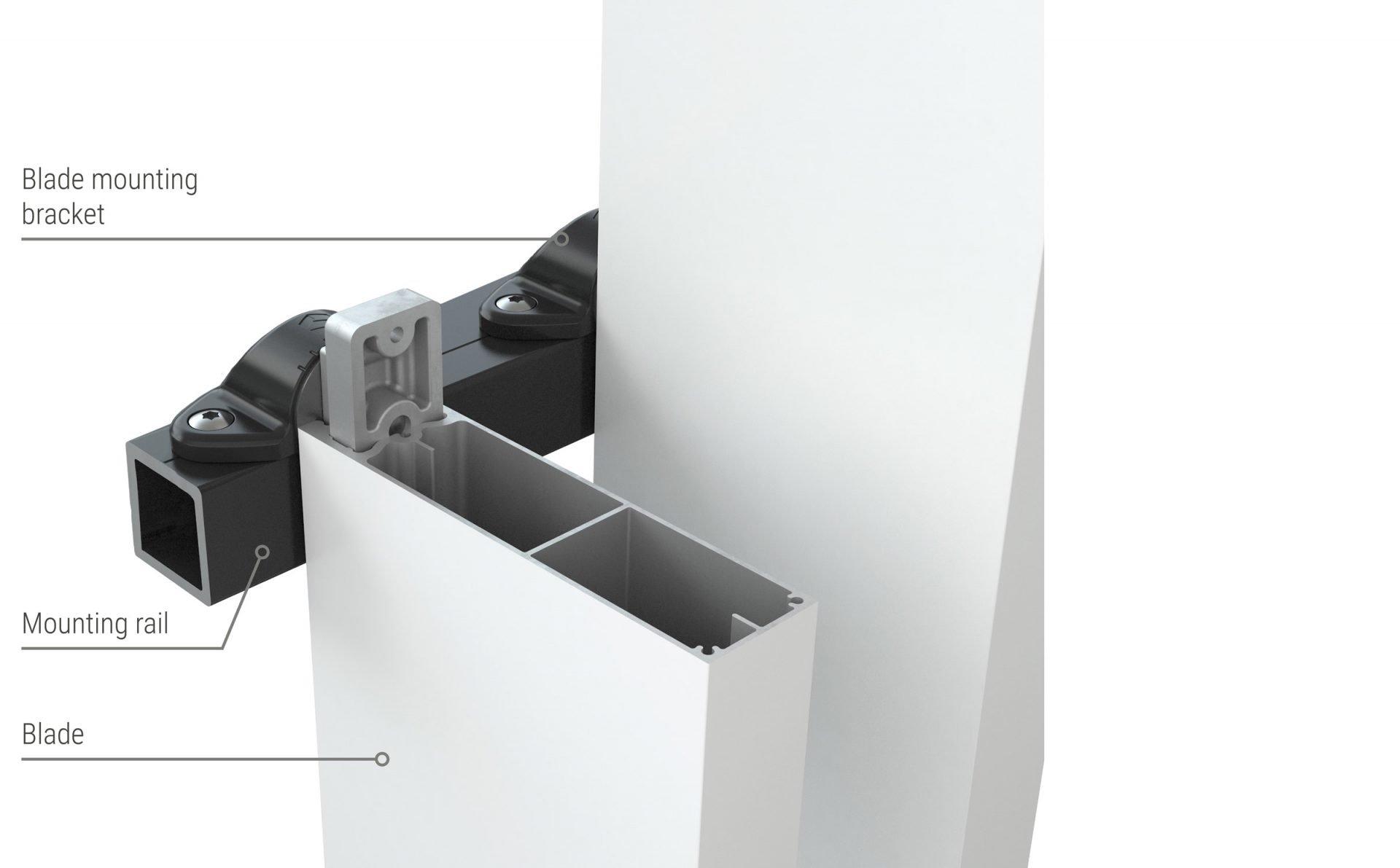
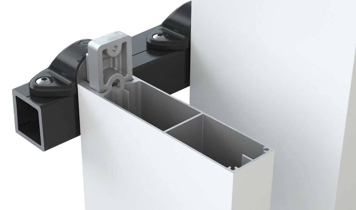
MOUNTING RAIL
Can be coloured to suit your needs and is available in a 50x50mm standard rail. Other sizes are avaIlable if larger spans required.
BLADE MOUNTING
BRACKET
- Lecast aluminium (ADC12)
- Centre bolt allows blades to pivot (installation non-perpendicular to rail)
FACADE BLADE TECH SPECS
This page includes comprehensive technical information on our Facade Blades system. Keep scrolling to browse or use the menu to find exactly what you are looking for.
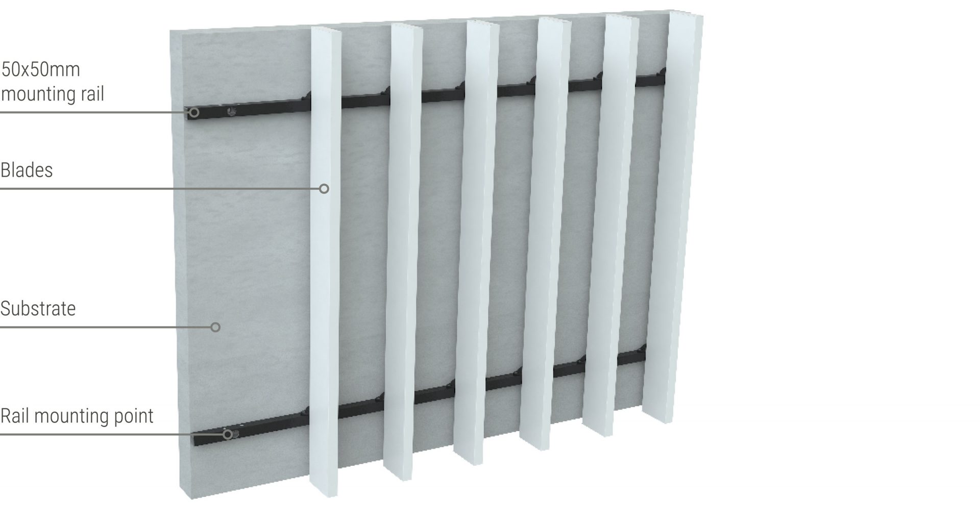
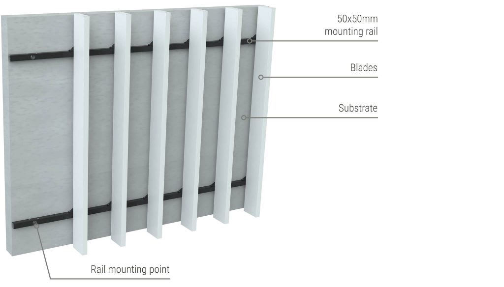
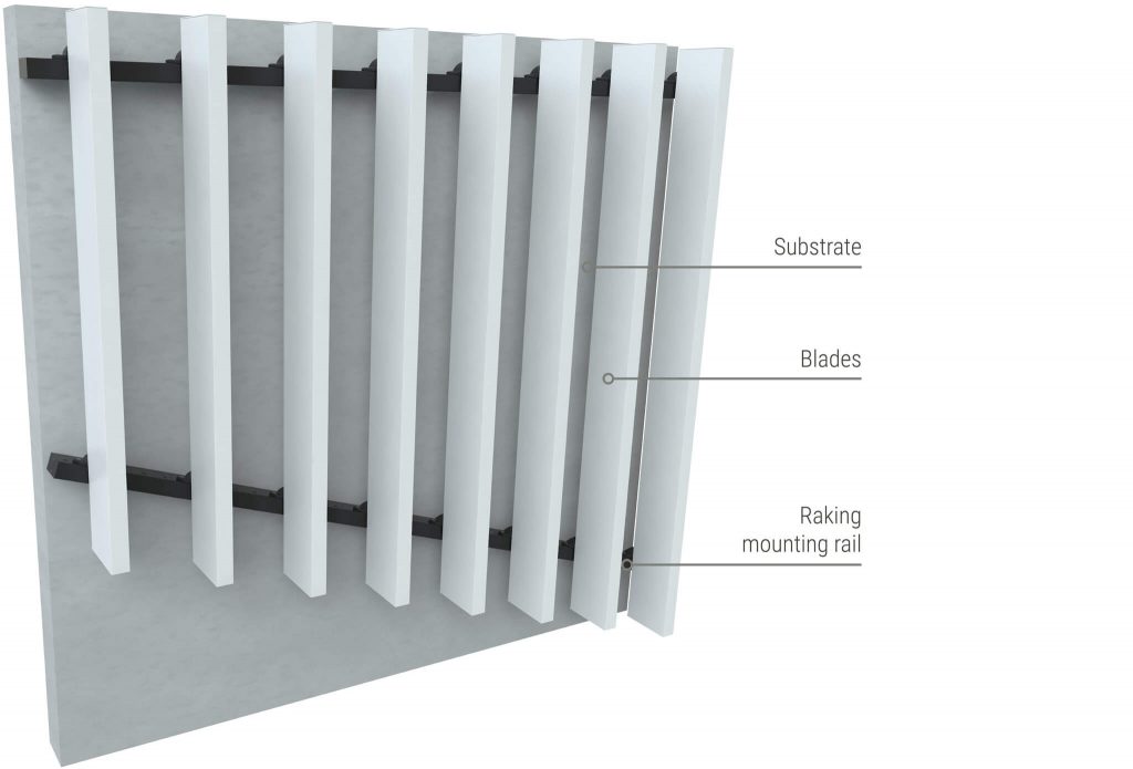
TYPICAL FACADE SETUP
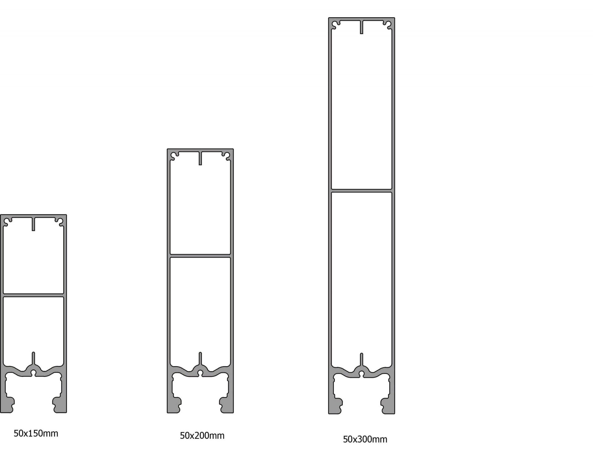
BLADES
Extruded Aluminium available in the following three sizes (see below):
- 50x150mm
- 50x200mm
- 50x300mm
MOUNTING OPTIONS
Sculptform's Facade Blade system has three mounting options to accomodate a variety of situations. Each option allows for both building and thermal movement to ensure the longevity of the facade.
DIRECT FIX - 50X50MM
The direct fix method uses a 50x50mm aluminium mounting rail which is suitable to be fixed to concrete or a steel structure.
BLADE SPACING OPTIONS
-Sculptform’s Facade Blades allow specifiers ultimate customisability when it comes to blade spacing. Typically blades are spaced with a 150-300mm gap between blades. -If the facade is acting as a balustrade, the maximum blade spacing is 125mm due to NCC regulations, the minimum blade spacing for all facade blade applications is 100mm. -Blade spacing is an effective element for value management, as small changes can have a significant impact on overall system cost.
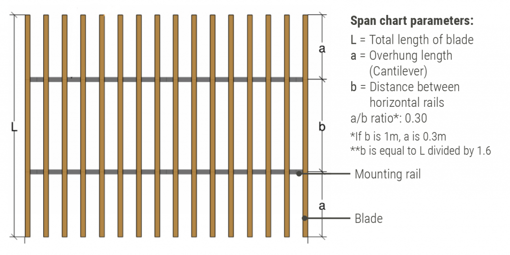
BLADE SPAN CHART
-This span chart is designed to be used by a qualified engineer. It covers the span and cantilever of vertical blades for a single span application, but not the connection of the mounting rail back to the building structure. -Only considers wind load, other loads (eg. Seismic and live loads) are not considered, as they will depend on the specific project site. -For a small fee Sculptform can do a preliminary engineering check for your project specifically. Contact us for more information.
MAXIMUM WIND PRESSURES (KPA) LENGTH (M)
| Blade Size (L) | 2.0 | 2.5 | 3.0 | 3.5 | 4.0 | 4.5 | 5.0 | 5.5 | 6.0 | 6.5 |
|---|---|---|---|---|---|---|---|---|---|---|
| 50x150mm | 9.5 | 7.6 | 6.3 | 5.4 | 4.7 | 4.2 | 3.8 | 3.4 | 3.1 | 2.9 |
| 50x200mm | 8.9 | 7.1 | 5.9 | 5.1 | 4.4 | 3.9 | 3.5 | 3.2 | 2.9 | 2.7 |
| 50x300mm | 5.5 | 4.4 | 3.7 | 3.1 | 2.7 | 2.4 | 2.2 | 2.0 | 1.8 | 1.7 |
DATA
-This span chart is based on a simply supported beam with two equal overhangs restraint condition (as shown above). -The span chart represents the maximum wind load in kPa that the respective blade size
can withstand. -Wind pressure tabulated above represents the wind pressure on the blade, which considers the drag coefficient of the blade and the local pressure coefficient. Note this is different to the site wind pressure. -The span chart is calculated based on the parameters as listed above. -The span chart above is for preliminary design only. Each project should verify the engineering for specific project purposes. -Rail length, number and type of fixings to the base building should be checked on a project-by-project basis. -Incidental load from building occupants/public/façade access activities have not been considered and need to be assessed project specifically. -The blades are assessed for deflection on the following limits: span/250, and span/125. For strength, the blades are assessed on the yield strength of 6063-T6 alloy (172 MPa); and the blade to rail brackets are assessed on the yield strength of 167 Mpa.
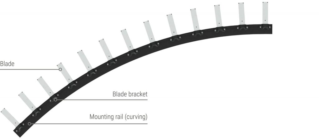
CURVING RAIL - MINIMUM RADIUS
The facade blade rail system can be factory curved to a minimum radius of 1.5 metres for both concave and convex curves when the 50x50mm rail is used.
RAKING MOUNTING RAIL
For more design freedom, the two part bracket allows to blade to be installed non-perpendicular to the rail. This creates opportunities for raking effects and angled blades on your facade with minimal blade cantilever.
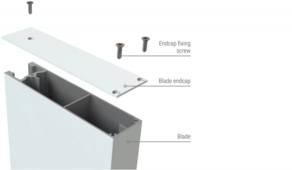
BLADE END CAPS
End caps are easily snapped in, with the added security of a locking off screw.
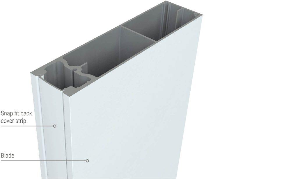
BACK COVER STRIP
To provide a seamless visual appearance to the back of the batten, back cover strips are provided which simply snap into the rear of the batten on site.
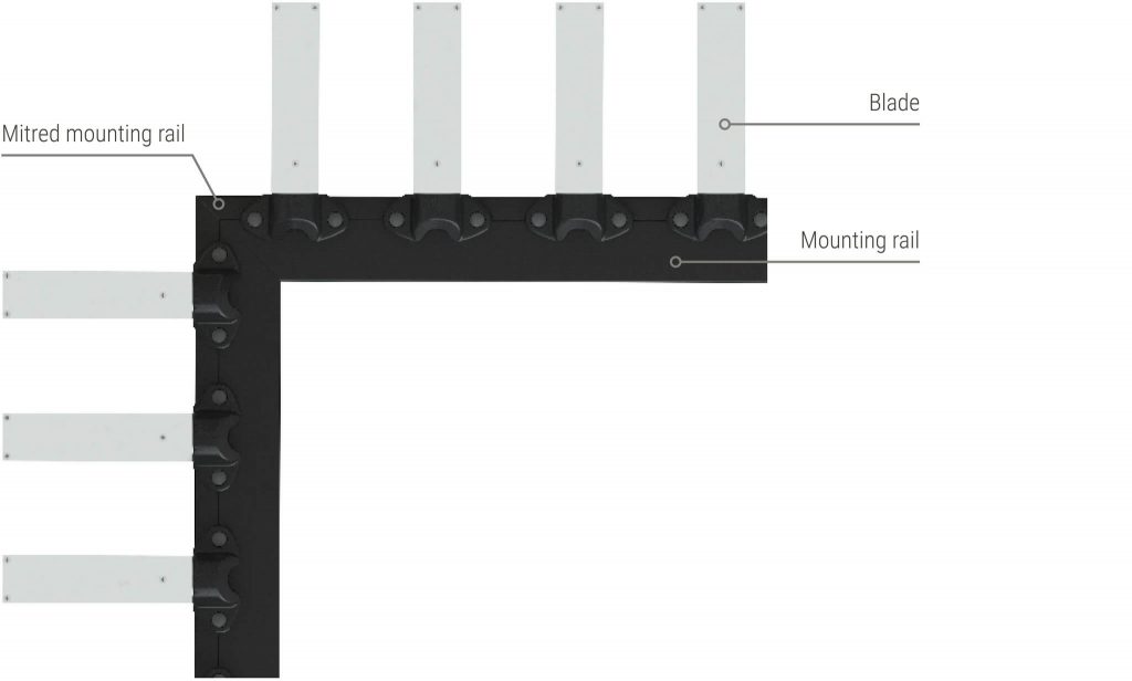
CORNER DETAILS
Set the fins in from the corner and mitre the rail
When wrapping blades around a 90-degree corner, the recommended option is to set the fins in from the corner and mitre the rail.
SIMPLE INSTALLATION
We understand site time is expensive. So we’ve developed the system to be simple, adaptable and easy to install on-site. A clean install with little or no fixings visible, with great performance.
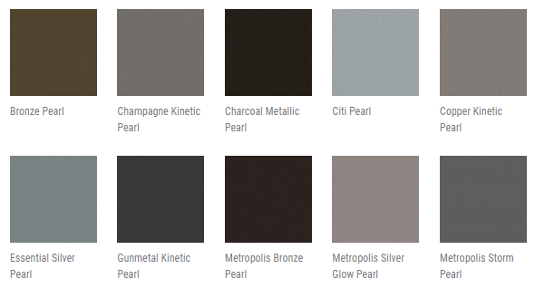
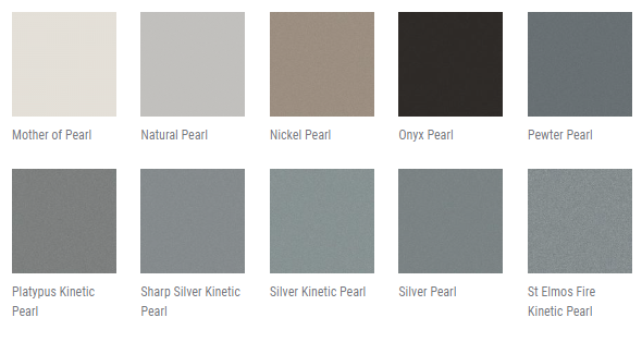
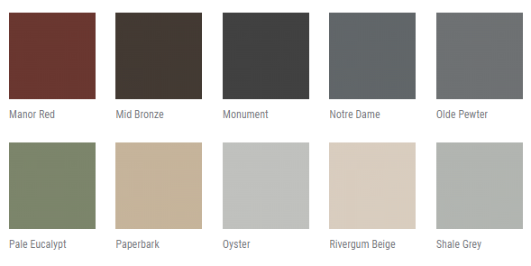
FINISHES
COLORS
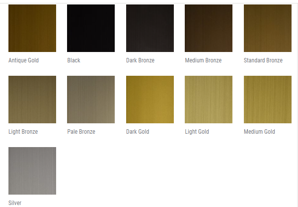
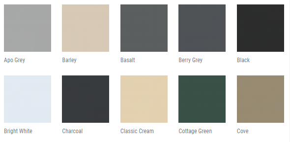
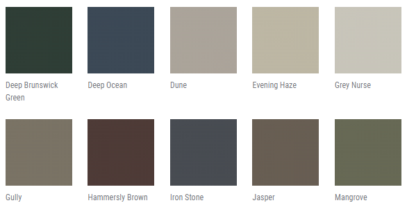
-Colours have been reproduced as accurately as possible, we recommend that you request product samples before making your final selection. -Please note: Lead times for product samples vary from 1-3 weeks for finishes depending on colour selected. Colour swatches are available for urgent requests. Please contact us for more information.
ANODISED
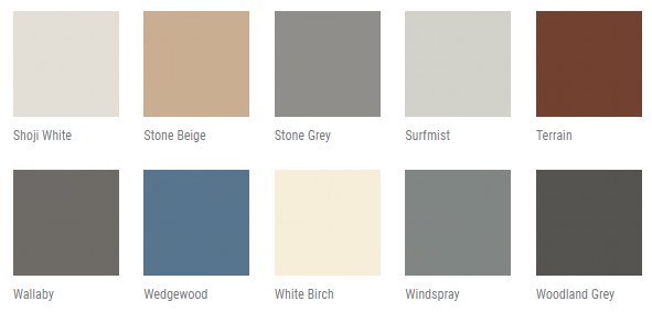
POWDERCOAT - DURALLOY
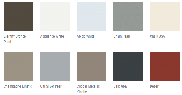
POWDERCOAT - DURATEC
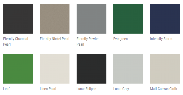
POWDERCOAT - PRECIOUS